- Tel: 0086 13501592453
- Email: sales@consnant.com


What Are You Looking For?


SPECIFICATION:
Model Number: TSS-48400
Pv input: MCB 25A / 2P * 8, DC-SPD * 8
Battery access: MCB 125A / 1P * 4
DC output: DC-SPD * Class 1-C
Secondary load disconnect: MCB 100A / 1P * 2,63A / 1P * 4,32A / 1P * 2
Primary load disconnect: MCB 63A / 1P * 2,32A / 1P * 2,16A / 1P * 2
Secondary load disconnect is controlled by the 400A contactor (normally closed)
Primary load disconnect is controlled by the 200A contactor (normally closed)
Note: above configurations can be customized.
Application field:
Telecom;
Data center
Item No :
TSS-48400Order(MOQ) :
1 pcsPayment :
T/TProduct Origin :
ChinaColor :
BlackShipping Port :
ShenzhenLead Time :
1-2 weeksWeight :
30 Kg48V 400A Embedded Telecom Power System
Description
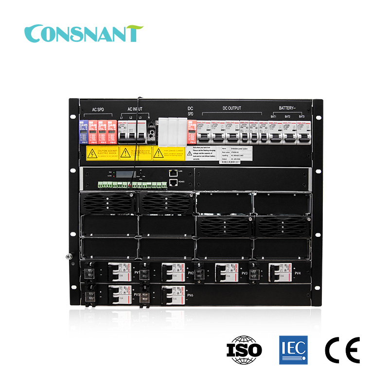
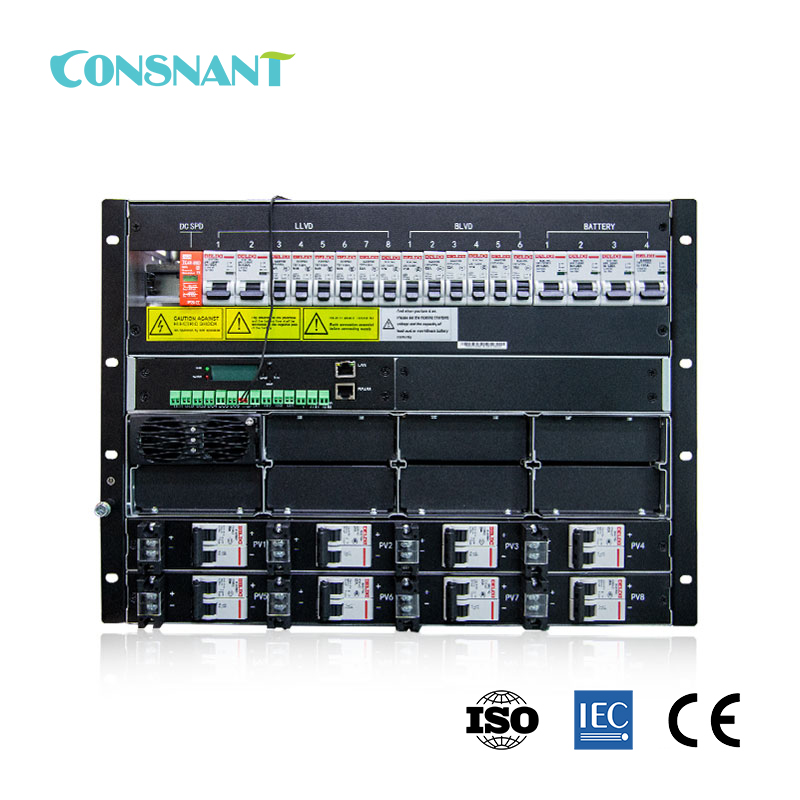
TSS-48400 embedded high-voltage photovoltaic power supply is a new generation of highly reliable and high-performance pure photovoltaic power supply system designed by the company based on years of development and online operation experience. The system configuration supports hot-swappable 1-8 photovoltaic modules. The system monitoring module has battery management function and power supply system monitoring function. Appropriately configured sensors can realize environmental monitoring, and provide multiple sets of backup monitoring quantities. It can provide RS485 communication interface to facilitate remote monitoring and unattended operation.
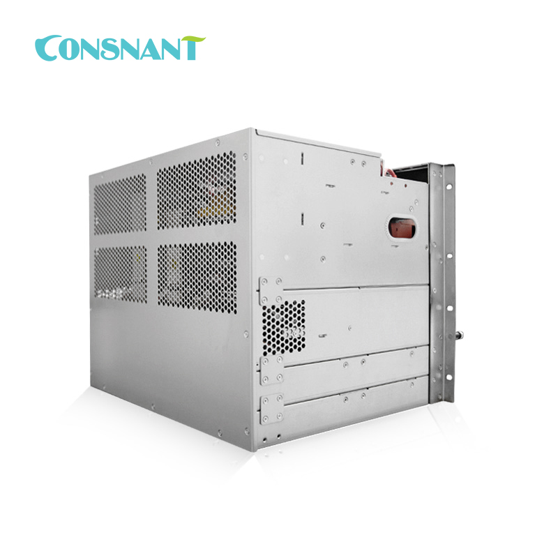
This embedded power supply is mainly used in outdoor cabinets.
Main product specifications
|
|
Input voltage range |
Output voltage |
Output(MAX) |
Output maximum power |
Configuration quantity |
|
|
Solar Charge Controller Module |
120~425Vdc |
-54.5V d c |
400A |
24KW |
1 (Full match 8) |
|
|
Configure |
||||||
|
Pv input: MCB 25A / 2P * 8, DC-SPD * 8 Battery access: MCB 125A / 1P * 4 DC output: DC-SPD * Class 1-C Secondary load disconnect: MCB 100A / 1P * 2,63A / 1P * 4,32A / 1P * 2 Primary load disconnect: MCB 63A / 1P * 2,32A / 1P * 2,16A / 1P * 2 Secondary load disconnect is controlled by the 400A contactor (normally closed) Primary load disconnect is controlled by the 200A contactor (normally closed) |
Specific configuration: it can be customized according to the customer
|
|||||
Principle introduction
The principle of TSS-48400 embedded high-voltage photovoltaic power supply system is as follows:

The system power supply is provided by 8 sets of pv input to the 8 PV modules and the negative electrode, and the first circuit connects to the secondary load input end, the second circuit and the third circuit connects to the negative end through the protection of the battery under the control of the monitoring; the PV module rectified output connects to the positive electrode of the battery.
Environmental Conditions
|
Enviromental parameter |
Operating environment conditions |
Transportation environmental conditions |
Storage environmental conditions |
Remarks |
||
|
Project |
Parameter |
|||||
|
Climate conditions |
Temperature |
Low temperature |
-40℃ |
-40℃ |
-45℃ |
-40℃ full load start, + 50~ + 75℃ linear drop |
|
High temperature |
50℃ |
70℃ |
70℃ |
|||
|
Humidity |
Low relative humidity |
5% |
/ |
5% |
/ |
|
|
High relative humidity |
95% |
/ |
95% |
|||
|
Condensation |
Not have |
/ |
not have |
|||
|
Altitude |
4000m |
4000m |
|
3000~4000 capacity reduction output |
||
|
Mechanical stress conditions |
Vibrate |
Sinusoidal vibration: 5~9Hz: amplitude of 3.5mm; 9~200Hz: acceleration of 10 m/s2; 3 Axial, sweep 5 vibration in each direction |
2~10Hz :30m2/s3; 10~200Hz :3m2/s3; 200~500Hz :1m2/s3; 3 Axial, 30min in each direction |
/ |
For the plug-in frame only, take out the rectifier module and the monitoring module during testing |
|
|
Impact (collision) |
Acceleration of 250 m/s2; Pulse width: 6ms; 3 axis 6 to each collision 500 times |
Acceleration of 400 m/s2; Pulse width: 6ms; 3 axis 6 to each collision 500 times |
/ |
|||
|
Drop |
/ |
Drop height of 1m; bottom surface 1 time |
/ |
|||
|
Cooling method |
Module forced air cooling |
Wind comes in from the front and comes out from the back |
||||
System Structure and Layout Drawing:

Technical Parameters
|
1.Input characteristics |
|||||
|
ON. |
Project |
Technical requirement |
Remarks |
||
|
1.1 |
Module input |
120 ~ 425Vdc (starting voltage over 160Vdc) |
|
||
|
1.2 |
Rated input voltage |
340Vdc |
|
||
|
1.3 |
MPPT voltage range |
120Vdc to 340Vdc |
|
||
|
1.4 |
Maximum input current |
17A |
|
||
|
1.5 |
Anti-polar protection |
Wrong input polarity, no damage |
|
||
|
1.6 |
Input insurance |
Positive and negative insurance |
|
||
|
1.7 |
Maximum input voltage |
450Vdc |
The power supply cannot be damaged |
||
|
ON. |
Project |
Technical requirement |
Remarks |
||
|
2.1 |
Output voltage range |
-42Vdc ~ -58Vdc (typical value-54.5Vdc) |
|
||
|
2.2 |
Module output rated current |
55A |
@-48VDC |
||
|
2.3 |
Module output peak current |
62.5A |
|
||
|
2.4 |
Voltage stabilization accuracy |
≤±1% |
|
||
|
2.5 |
Output ripple & noise |
≤200mVp-p |
Rated input voltage and load and bandwidth limit of 20 MHz |
||
|
2.6 |
Efficiency |
≥95% |
@340/40%~70% Load -54.5Vdc |
||
|
2.7 |
Startup time |
3~10S |
The rated input voltage starts to the output voltage establishes to the setting value, the starting output needs to use the pre-flow limit function |
||
|
2.8 |
On/off overshoot amplitude |
≤±5% |
When either module is hot plugged (the load current should not be greater than the total output current in the working module), the system output voltage fluctuates |
||
|
2.9 |
Dynamic response |
Overshoot range |
≤±5% |
25%~50%~25% or 50%~75%~50% load variation |
|
|
Recovery time |
≤200µS |
||||
|
2.10 |
Temperature coefficient |
≤±0.02%/℃ |
|
||
|
2.11 |
Psophometrically weighted noise voltage |
≤2mV |
|
||
|
2.12 |
Wide-band noise voltage |
3.4~150KHz |
≤50mV |
|
|
|
0.15~30M Hz |
≤20 |
|
|||
|
2.11 |
Discrete noise voltage |
3.4~150KHz |
≤5mV |
|
|
|
150~200KHz |
≤3mV |
|
|||
|
200~500KHz |
≤2mV |
|
|||
|
0.5~30M Hz |
≤1mV |
|
|||
|
2.12 |
Voltage drop |
≤500mV |
|
||
|
ON. |
Project |
Technical requirement |
Remarks |
||
|
3.1 |
Photovoltaic input overvoltage protection |
430Vdc |
Can self-recovery, the difference of not less than 15 Vac |
||
|
3.2 |
Photovoltaic input undervoltage protection |
110Vdc |
Can self-recovery, the difference of not less than 40 Vac |
||
|
3.3 |
Photovoltaic output overvoltage protection |
Internal-58.5Vdc to-60.5Vdc, external: 63Vdc |
Lock, can not recover, need to restart |
||
|
3.4 |
Output undervoltage protection |
Battery disconnect protection |
Through monitoring, the battery can be powered down, and the protection point can be set |
||
|
3.5 |
Output limit protection |
Have |
|
||
|
3.6 |
Output short circuit protection |
Have |
Long-term short circuit, can recover from itself |
||
|
3.7 |
Overtemperature protection |
It can recover automatically at the ambient temperature of 75℃ |
|
||
|
3.8 |
Battery polarity is connected to reverse protection |
Not have |
According to the user needs can have the battery polarity reverse connection protection function |
||
|
3.9 |
PV underpower protection |
Input power <50W and shutdown for 5 minutes |
The module starts when the input voltage is greater than 160 Vdc for 5 minutes. |
||
Tags :
 Sign Up To Our Newsletters
Tel : 0086 13501592453
Email : sales@consnant.com
Address : Building B6, Junfeng Industrial Park, Yonghe Road, Fuhai Sub-District, Bao'an District, Shenzhen City, 518103, P.R.China
Copyright © 2025 Shenzhen CONSNANT Technology Co., Ltd. All Rights Reserved
 IPv6 network supported